

VBT-LB SERIES · COMPLETE LUBRICANT MANUFACTURING SOLUTION
Lubricating Oil
Blending & Filling Plant
Complete production line for base-oil storage, additive preparation, automatic metering, controlled blending, quality inspection, filtration and multi-format filling.
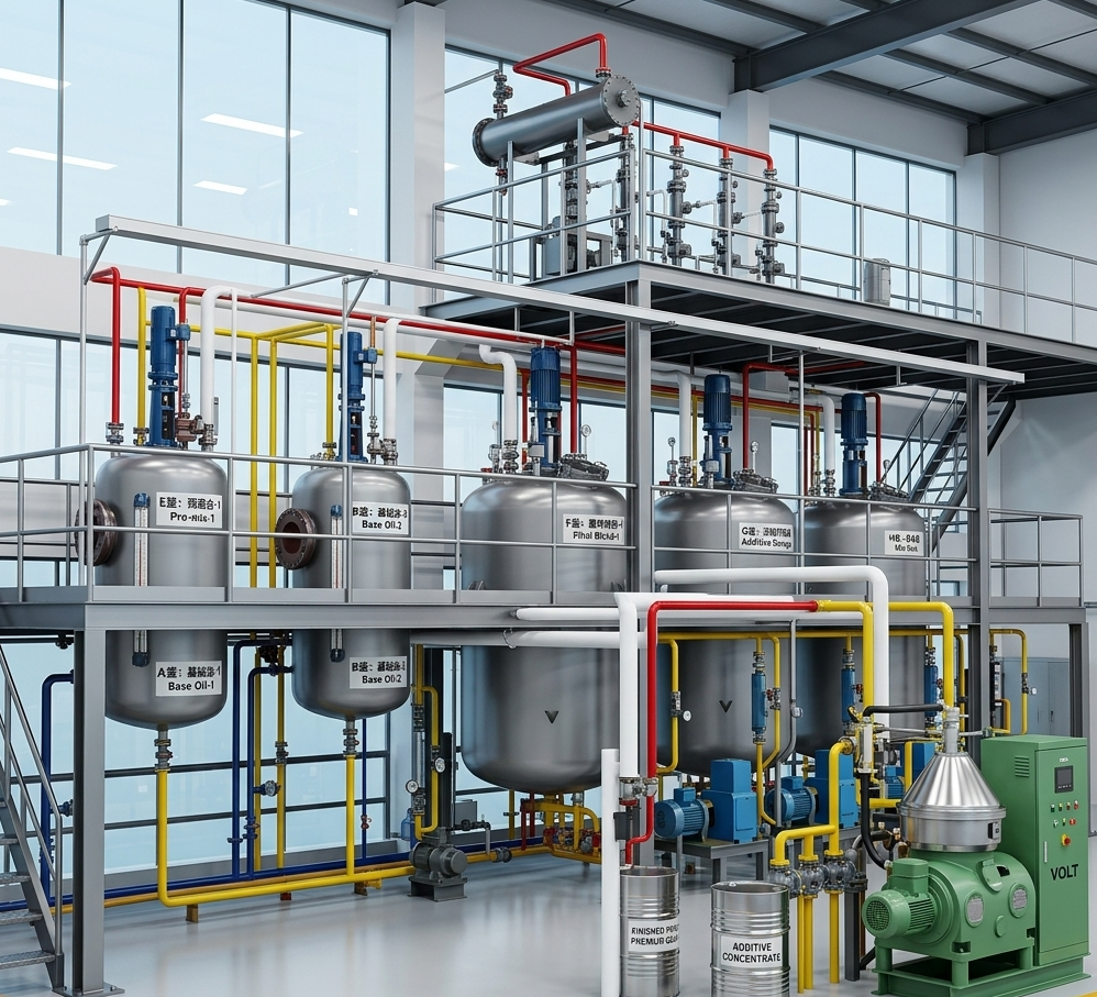
Project-Specific
CAPACITY AND VESSEL CONFIGURATION
Within ±0.5%*
REFERENCE BATCH DOSING ACCURACY
40–80°C*
TYPICAL BLENDING TEMPERATURE
1–1,000 L
STANDARD FILLING RANGE
Reference values. Final performance is confirmed from the selected instruments, recipe, ingredient quantity and product properties.
——– 01 · COMPLETE PRODUCTION LINE
Complete Lubricating Oil Production Line
VBT-LB covers the complete route from raw-material receiving to finished-product packaging. The blending and filling sections are engineered as the main production center, while storage, utilities and control systems are integrated around them.
01
Raw-Material Release
02
Recipe Execution
03
Blend Control
04
Representative Sample
05
Correction
06
Finished-Oil Release
MATERIAL IN
Base Oils and Additives
Received, identified, sampled and routed to dedicated storage.
MAIN PRODUCTION CENTER
Metering, Blending and Quality Control
Recipes control dosing, temperature, mixing, circulation and release.
PRODUCT OUT
Packaged Finished Lubricants
Filtered and filled into the required retail or industrial package.
——– 02 · CORE FUNCTIONS
Core Functions of the Lubricant Blending Line
Each function has a defined operating method, control point and production result. The line is configured to execute the approved recipe repeatedly and record what happened in every batch.
01
Recipe Management
Authorized recipes define ingredient identity, target quantity, dosing order, temperature and blending time.
Version control · User permissions
Prevents unapproved formula changes.
02
Automatic Metering
Base oils use load cells or mass flowmeters; additives use dedicated weighing or small-dose systems.
Reference accuracy: within ±0.5%*
Records target and actual quantities.
03
Uniform Blending
Mechanical agitation works with external circulation to reduce concentration and temperature differences.
Typical temperature: 40–80°C*
Produces a uniform batch before testing.
04
Clean Product Changeover
Drainable piping, defined flush routes and product campaign planning reduce residual material.
Drain · Flush · Recover · Verify
Reduces cross-contamination and product loss.
05
Batch Traceability
Raw-material lots, recipe version, dosing, temperature, time, alarms and release records remain connected.
One batch number · One record
Allows every finished batch to be traced.
06
Multi-Format Filling
Released lubricant is routed to the required small-pack, pail, drum or IBC filling system.
1–1,000 L
Supports retail and industrial packaging.
* Reference values are confirmed during engineering. Small-dose additives may require a dedicated high-precision weighing system.
——– 03 · PRODUCTION PROCESS
Lubricating Oil Blending Process
Select a production stage to see the incoming material, equipment, operating method, control requirement and completed result.
01
SELECTED PROCESS STAGE
Base Oil Storage
Material
Base oils delivered by tanker, drum or IBC
Equipment
Unloading pump, transfer filter, dedicated storage tanks and level instruments
Operation
Identify, sample, filter and transfer each base oil into the assigned storage tank.
Control
Tank identity, material lot, high-level alarm and transfer route confirmation
Result
Verified base oil available for recipe dosing
02
SELECTED PROCESS STAGE
Additive Preparation
Material
Additive packages and individual additives
Equipment
Drum/IBC unloading system, additive storage, preheating and insulated piping
Operation
Identify and condition additives before dosing; high-viscosity materials are preheated where required.
Control
Material identification, temperature limit and line selection
Result
Additives prepared at the required handling condition
03
SELECTED PROCESS STAGE
Automatic Metering
Material
Base oils and additives required by the selected recipe
Equipment
Load cells, mass flowmeters, metering vessels, automatic valves and PLC
Operation
Fast dosing changes to slow dosing near the target, followed by final trim and deviation confirmation.
Control
Reference batch dosing accuracy within ±0.5%; final accuracy depends on selected instruments and dose size
Result
Target and actual quantities recorded before blending
04
SELECTED PROCESS STAGE
Heating and Blending
Material
Metered base oils and additives
Equipment
Jacket/coil, agitator and steam, thermal-oil or electric heating system
Operation
Heat, agitate and hold the batch according to the authorized product recipe.
Control
Typical blending temperature 40–80°C; formula-specific setpoint, overtemperature alarm and heating interlock
Result
Components fully dispersed under controlled temperature and time
05
SELECTED PROCESS STAGE
Circulation and Homogenization
Material
Blended lubricant in the working vessel
Equipment
Mechanical agitator, external circulation pump and return manifold
Operation
Agitation and external circulation reduce concentration and temperature differences throughout the batch.
Control
Recipe-defined circulation time; sampling confirms batch uniformity
Result
Uniform batch ready for laboratory verification
06
SELECTED PROCESS STAGE
Quality Inspection
Material
Representative finished-batch sample
Equipment
Sampling point and customer laboratory/test instruments
Operation
Hold the batch until viscosity, appearance and project-defined quality indicators are accepted.
Control
Unreleased batches are blocked from finished-product transfer and filling
Result
Approved batch linked to its laboratory record
07
SELECTED PROCESS STAGE
Filtration and Filling
Material
Quality-released finished lubricant
Equipment
Polishing filter, finished-product tank and selected filling line
Operation
Filter, transfer and fill the product into 1–5 L packs, 18–20 L pails, 200 L drums or 1,000 L IBCs.
Control
Package-specific filling setpoint, batch coding and quantity record
Result
Traceable finished product ready for storage or dispatch
——– 04 · LINE CONFIGURATIONS
Production Line Configurations for Different Capacities and Products
The production line is selected from batch size, daily or annual output, product variety, changeover frequency and filling schedule—not from one fixed machine model.
SELECTED CONFIGURATION
Single-Vessel Batch Line
Suitable For
Focused product range and smaller production program
Main Equipment
One blending vessel with shared dosing, filtration and filling
Main Benefit
Simple material routing, compact footprint and lower initial investment
Engineering Note
Production pauses during cleaning and product changeover.
SELECTED CONFIGURATION
Multi-Vessel Parallel Line
Suitable For
Several lubricant grades and frequent production scheduling
Main Equipment
Independent blending vessels with shared or dedicated dosing routes
Main Benefit
Different batches can be produced in parallel
Engineering Note
Piping segregation and changeover planning are defined during engineering.
SELECTED CONFIGURATION
Coordinated Multi-Vessel Batch Line
Suitable For
A large master batch produced through several smaller vessels
Main Equipment
Multiple blending vessels plus a common final homogenization tank
Main Benefit
Several sub-batches are linked to one master recipe and final batch record
Engineering Note
Final consolidation and homogenization are required before release.
SELECTED CONFIGURATION
Continuous Inline Blending Line
Suitable For
Stable, high-volume production with repeatable recipes
Main Equipment
Continuous component metering, inline mixer and verification system
Main Benefit
High throughput and reduced batch turnaround
Engineering Note
Metering accuracy, online verification and feed stability require project-specific engineering.
——– 05 · METERING AND BLENDING TECHNOLOGY
Automatic Metering, Controlled Heating and Uniform Blending
The system meters each ingredient, controls the blending temperature and combines agitation with external circulation. These functions determine whether the approved formula is reproduced consistently.
01 · AUTOMATIC METERING
How Base Oils and Additives Are Metered
Base oils are measured by vessel weighing or mass flowmeters. Additives use dedicated weighing vessels or small-dose systems. Fast dosing changes to slow dosing near the target, followed by final trim.
Reference batch accuracy: within ±0.5%
PLC record: target quantity, actual quantity and deviation
Deviation control: stop the next step and generate an alarm
Why it matters: protects formula accuracy, product quality and additive cost
02 · CONTROLLED HEATING
Steam, Thermal Oil or Electric Heating
The heating method is selected from vessel size, heat-up time, local energy supply and product viscosity. The recipe defines the temperature setpoint and holding time.
Typical blending temperature: 40–80°C, product dependent
Automatic control: heat, hold and stop at the recipe setpoint
Safety control: overtemperature alarm and heating shutdown
Available options: steam, thermal oil or electric heating
03 · UNIFORM BLENDING
Agitation and External Circulation
The agitator disperses components inside the vessel while the external circulation loop moves product through the full working volume. Together they reduce temperature and concentration differences.
Mixing method: mechanical agitation plus pump circulation
Operating time: defined by product recipe and batch size
Uniformity check: representative sampling and laboratory verification
High-viscosity products: stronger agitation, heating and transfer configuration
04 · PRODUCT CHANGEOVER
Drain, Flush, Recover and Verify
Changeover design reduces residual product in common piping. The operating procedure is selected from product compatibility and contamination risk.
Line design: short common routes and low-point drains
Cleaning: controlled circulation flushing where required
Recovery: segregated collection of flushing oil
Verification: valve route and first-product check before release
——– 06 · BATCH TRACEABILITY
Production Data Recorded for Every Lubricant Batch
The control system connects the finished-product batch number to the raw materials, approved recipe, actual operating data, quality release and filling record.
01 Raw-material name and lot number
02 Authorized recipe and version
03Target and actual dosing quantities
04 Dosing deviation and operator confirmation
05 Blending temperature and holding time
06 Agitation and circulation time
07 Alarm and manual-operation history
08 Laboratory release result
09 Finished-product batch number
10 Package size and filled quantity
Result
Every finished-product batch can be traced back to its raw materials, formula, production parameters and quality record.
——– 07 · FILLING AND PACKAGING
Filling Systems for 1–1,000 L Lubricant Packages
The filling system is selected from package size, required output, filling accuracy, automation level and downstream packaging method.
01
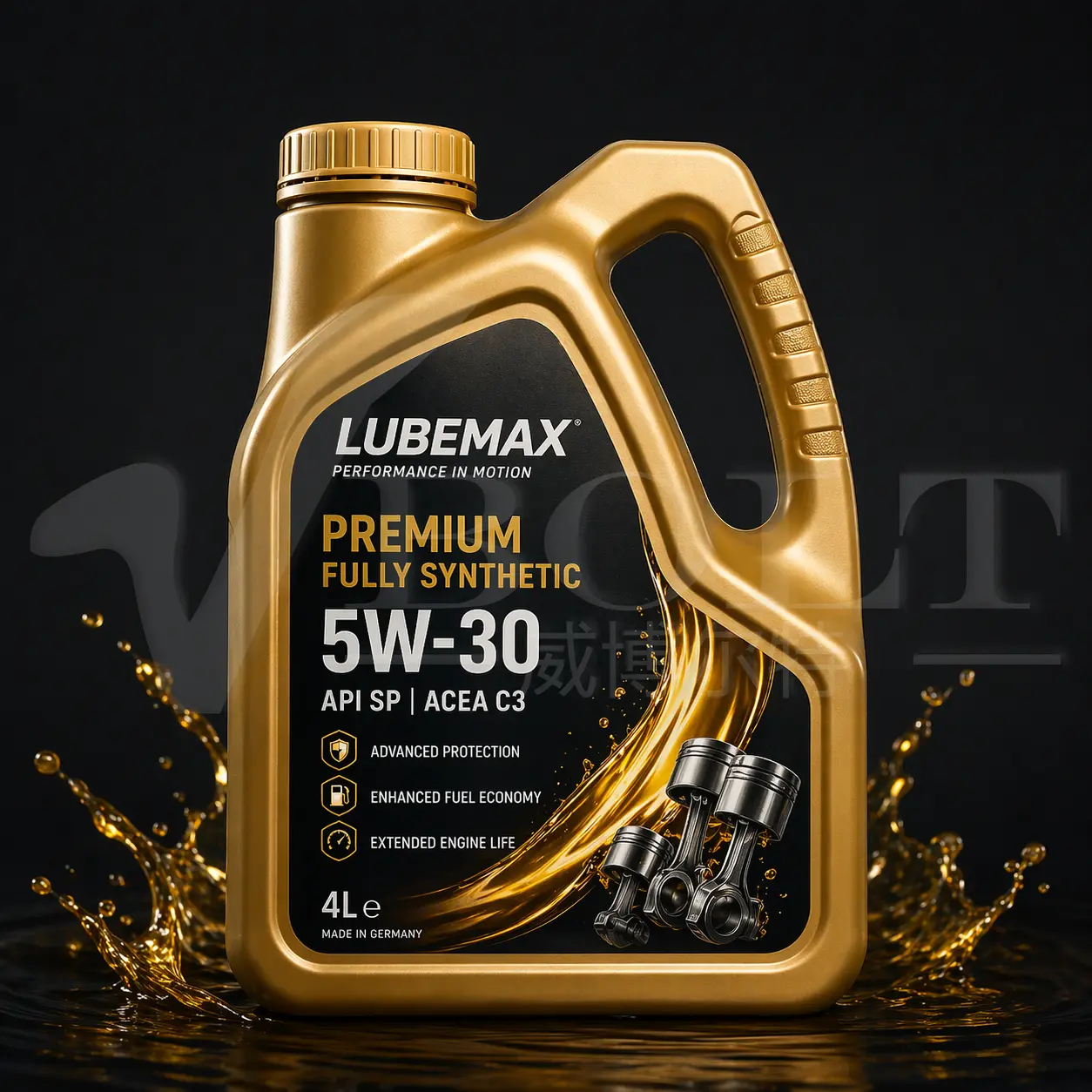
1–5 L · Small Packages
Metering: Volumetric or weighing filling
Configuration: Multiple filling heads, capping, labeling and coding
Reference weighing-fill accuracy: within ±0.5%*
02
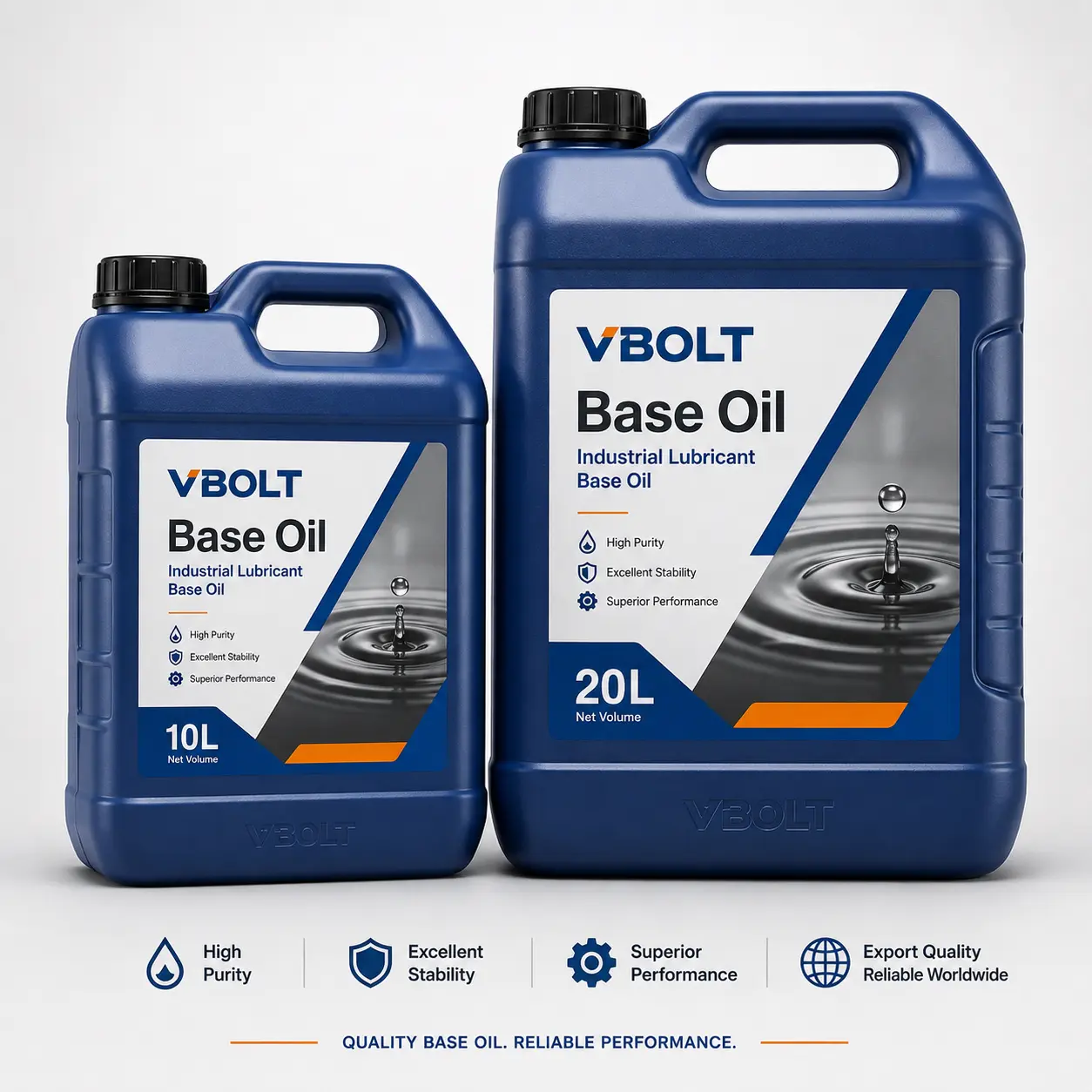
18–20 L · Pails
Metering: Weighing filling
Configuration: Container positioning, filling, lid placement and pressing
Reference weighing-fill accuracy: within ±0.5%*
03
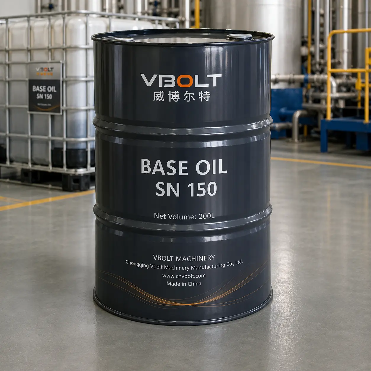
200 L · Drums
Metering: High-flow weighing filling
Configuration: Two-stage filling, drip control and batch coding
Reference weighing-fill accuracy: within ±0.5%*
04
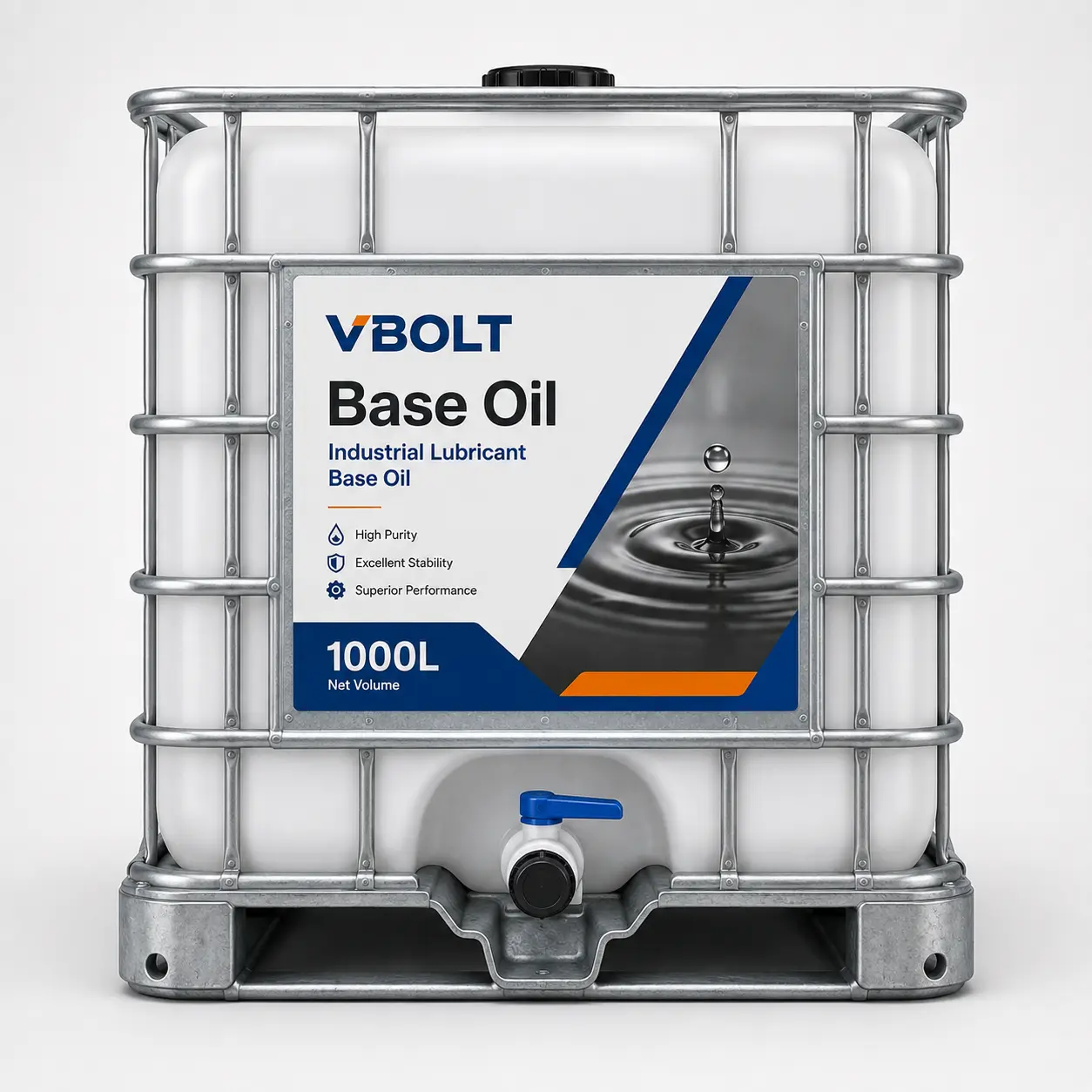
1,000 L · IBC
Metering: Bulk weighing filling
Configuration: High-flow transfer, weight confirmation and dispatch record
Reference weighing-fill accuracy: within ±0.5%*
Filling accuracy and output depend on package size, product viscosity, filling machine and weighing system. Final values are confirmed in the technical proposal.
——– 08 · APPLICABLE PRODUCTS
Lubricants Produced by the VBT-LB Line
Each product requires the correct heating, agitation, filtration and cleaning configuration. Product properties—not only plant capacity—determine the equipment selection.
01
Engine Oil
Multiple additives and strict recipe control
Automatic dosing and batch traceability
02
Hydraulic Oil
Cleanliness and filtration are important
Fine filtration and clean transfer route
03
Gear Oil
Higher viscosity requires stronger handling
Heating, high-torque agitation and suitable pumps
04
Compressor Oil
Stable formulation and cleanliness
Controlled blending and polishing filtration
05
Industrial Lubricants
Wide viscosity and package range
Flexible vessel and filling configuration
06
Metalworking Oils
Product compatibility must be evaluated
Dedicated or carefully controlled changeover route
Transformer oil requires a dedicated configuration because moisture, cleanliness, vacuum treatment and segregation requirements differ from conventional lubricant blending.
——– 09 · PLC CONTROL AND INTERLOCKS
Automatic Control and Safety Interlocks
PLC and HMI coordinate recipes, pumps, valves, heating, vessel levels and filling permissions. Interlocks prevent the process from continuing when a required condition is not satisfied.
01
High Level
Stop incoming transfer and alarm
02
Low Level
Prevent pump dry running
03
Overtemperature
Stop heating and alarm
04
Dosing Deviation
Hold the recipe before blending
05
Valve Route
Confirm the selected transfer path
06
Quality Release
Block filling until approval
07
Motor Protection
Trip and display equipment fault
08
Manual / Auto
Controlled operating-mode selection
——– 10 · COMPLETE PLANT DELIVERY
From Plant Design to Commissioning and Operator Training
VBOLT can coordinate the complete lubricant factory, including production equipment, piping, electrical control and filling-line interfaces. The final supply boundary is defined in the contract.
01 Project Definition
Products, recipes, capacity, package sizes and site utilities
02 Engineering
Process flow, equipment, layout, piping, electrical and control design
03 Manufacturing
Core equipment fabrication, inspection and technical documentation
04 Site Integration
Installation guidance, interface coordination and commissioning
05 Production Support
Trial batches, operator training and technical service
VBOLT SCOPE
Process and equipment engineering, core equipment, control integration, documentation, installation guidance, commissioning and training as defined by contract.
CUSTOMER / LOCAL SCOPE
Factory building, civil works, external utilities, local fire protection, permits and other site responsibilities as defined by contract.
——– 11 · REFERENCE CONFIGURATION
15 T/Batch Coordinated Blending Line — Reference Example
This example explains how several blending vessels can form one coordinated production batch. It is not a fixed VBT-LB model; all capacities and equipment are project-specific.
MASTER BATCH
15 T/Batch
BLENDING VESSELS
5 × 3 T
BATCH CONTROL
1 Master Recipe
HEATING
Steam / Thermal Oil / Electric
FINAL PROCESS
Homogenize · Test · Filter
FILLING
1–1,000 L
Five vessel records are linked to one master batch. The streams are consolidated for final homogenization, quality inspection, filtration and filling.
——– 12 · TECHNICAL FAQ
Lubricant Blending Plant FAQ
Direct answers to the questions that determine equipment configuration, production capacity and product quality control.
——– 13 · PROJECT INQUIRY
Get Your Lubricant Blending Plant Configuration
Send the project basis. VBOLT will configure the storage, metering, blending, filtration, control and filling systems for your products and production plan.
01 Lubricant products and recipe types
02 Batch, daily or annual production capacity
03 Base oils, additives and viscosity range
04 Required package sizes and filling output
05 Available heating energy and electrical power
06 Project country and site conditions